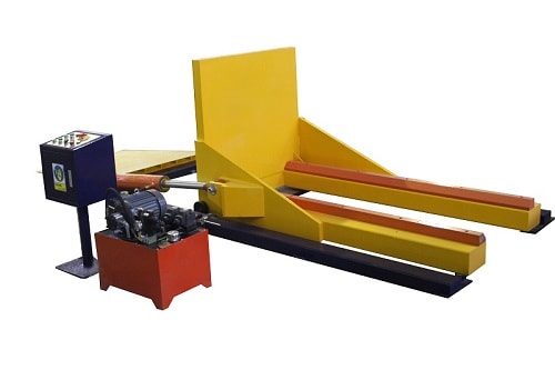
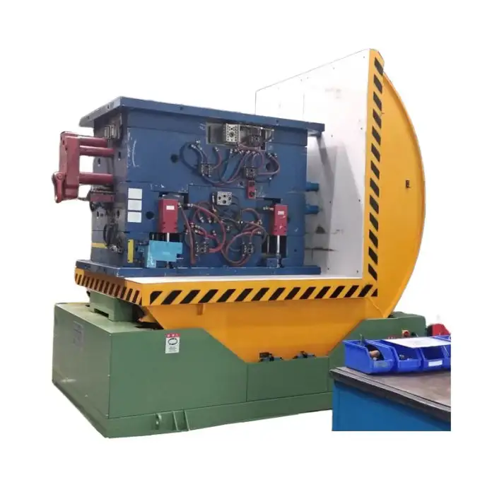
Installing a hydraulic mold upender is a straightforward process if you follow these steps: Begin by carefully unloading and positioning the upender, then securely bolt it to the floor. Next, connect any remote hydraulic and electrical components according to provided schematics. Finally, check hydraulic fluid levels, purge air from the system, and test operation to ensure smooth and safe mold handling.
Hydraulic mold upenders are indispensable pieces of equipment in facilities that handle heavy molds and dies. These machines streamline workflow, enhance safety, and significantly reduce the manual labor involved in turning over large, cumbersome molds. Investing in a hydraulic upender translates to improved productivity and a safer working environment. This guide provides a detailed, step-by-step approach to installing your new hydraulic mold upender, ensuring a smooth setup and years of reliable operation.
Preparing for Installation: Unloading and Positioning
Before diving into the technical details, it's crucial to properly unload and position your hydraulic upender. Bushman AvonTec upenders, and similar models, are typically shipped fully assembled, simplifying the initial setup.
Unloading:
The upender may arrive with lifting brackets pre-attached to its base frame. Utilize these brackets, if present, for unloading. Employ appropriately rated lifting equipment, such as an overhead crane or forklift with a suitable rigging, to lift the upender. If lifting brackets are not available:
- Sling Method: Carefully use four slings around the base frame of the machine.
- Corner Lifting: Ensure the slings are positioned to lift the upender evenly at each corner of the base frame to maintain balance and prevent stress on the machine's structure during unloading.
Positioning:
Selecting the right location for your hydraulic upender is crucial for operational efficiency and safety. - Level Surface: Choose a location with a level and solid floor capable of supporting the combined weight of the upender and its maximum rated load. Uneven surfaces can lead to operational instability and potential damage.
- Bolting Location: The base frame comes equipped with lag-down brackets. Plan the upender's position so these brackets can be effectively used to bolt the machine to the floor.
- Operational Space: Ensure ample clearance around the upender. Consider the space required for loading and unloading molds using forklifts, cranes, or other material handling equipment. Leave sufficient room for the upender's full 90-degree rotation, accounting for the largest molds you intend to handle.
- Power Access: Plan the placement in proximity to a suitable power supply. This is particularly important if your upender has a remote power unit, to ensure efficient connection of hydraulic and electrical lines.
Step-by-Step Installation Guide
With the upender safely unloaded and positioned, you can proceed with the detailed installation steps.

Step 1: Securely Bolting the Upender
Anchoring the hydraulic upender to the floor is paramount for stability and safe operation.
- Lag-Down Brackets: Locate the lag-down brackets on the upender’s base frame. These are specifically designed for bolting the unit to the floor.
- Bolt Selection: Use appropriately sized Grade 8 bolts or equivalent high-strength fasteners. Consult the manufacturer's manual for specific bolt size recommendations if available.
- Drilling and Anchoring: Mark the locations for bolt holes on the floor using the lag-down brackets as a template. Drill holes into the floor, ensuring they are of the correct diameter and depth for the chosen bolts and floor type.
- Tightening: Position the upender in its designated location and align the lag-down brackets with the drilled holes. Insert the bolts and tighten them securely. This firmly mounts the upender to the floor, preventing movement during operation.
Step 2: Connecting a Remote Power Unit (If Applicable)
Some hydraulic upenders utilize a remote power unit. If your model has a separate power unit, hydraulic and electrical connections are necessary. - Hydraulic Line Identification: Locate the hydraulic ports on both the power unit and the hydraulic manifold on the upender base. These ports are typically identified with markings or labels.
- Correct Port Matching: Carefully connect the hydraulic lines, ensuring that corresponding ports are linked (e.g., pressure port on the power unit to the pressure port on the manifold). Use hydraulic lines of the specified type and pressure rating, ideally those supplied by the manufacturer or recommended for the upender.
- Secure Connections: Tighten all hydraulic fittings to prevent leaks. Ensure connections are snug but avoid over-tightening, which can damage fittings or lines.
Step 3: Establishing Electrical Control Circuit Connections (If Applicable)
For remote power units, electrical control circuits need to be connected to enable operation from the upender's control pendant. - Junction Box Location: Find the junction box located in the base of the upender. This box contains a terminal strip for control circuit connections.
- Terminal Strip Matching: Identify the numbered terminals on the terminal strip within the upender’s junction box and the corresponding numbered terminals in the power unit’s control box.
- Wiring Based on Schematic: Refer to the electrical schematic provided in the service manual. Connect wires between the matching numbered terminals in the upender junction box and the power unit control box, following the schematic precisely. This establishes the control signals for upender operation.
Step 4: Powering Up the System
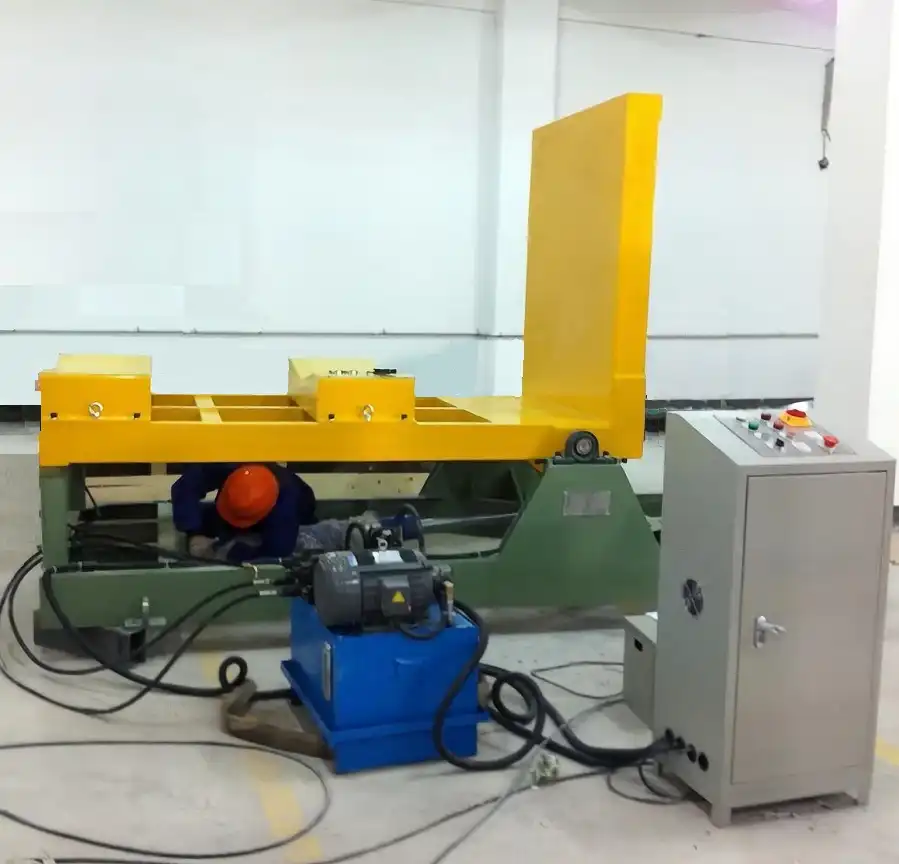
Connecting the electrical power supply is the next critical step. This task should be performed by a qualified electrician, adhering to all local and national electrical codes.
- Power Disconnect Switch: Install a power disconnect switch near the upender location. This switch allows for safe disconnection of power for maintenance or emergencies.
- Wiring to Motor Starter: Connect the incoming power leads from the disconnect switch to the magnetic motor starter located in the power unit’s control box. Typically these are connected to terminals labeled L1, L2, and L3.
- Grounding: Ensure proper grounding of the upender and power unit according to electrical safety standards.
- Motor Rotation Check: After initial wiring, briefly energize the power. Observe the hydraulic pump motor’s direction of rotation. If the pump runs in reverse (often indicated by unusual noise or lack of hydraulic pressure), immediately disconnect power and reverse the L1 and L3 power leads to correct the motor rotation. Correct motor rotation is crucial for proper hydraulic system operation.
Step 5: Hydraulic Fluid Check and System Charging
Before operating the upender under load, ensure the hydraulic system is properly filled and charged. - Hydraulic Fluid Reservoir: Locate the hydraulic fluid reservoir on the power unit.
- Fluid Level Check: Check the hydraulic fluid level in the reservoir. It should be within the recommended range, typically indicated by level marks on the reservoir or a sight glass.
- Fluid Top-Off (If Needed): If the fluid level is low, add the recommended hydraulic fluid as specified in the manual. Use the correct type of hydraulic fluid to maintain system performance and longevity.
- System Charging: After connecting hydraulic lines and verifying fluid level, briefly operate the upender controls (without a load) to start the hydraulic pump and circulate fluid throughout the system. This charges the hydraulic lines and cylinders.
Step 6: Initial Operation and Air Purging
Once hydraulic and electrical connections are complete, perform initial operational checks. - Control Pendant Operation: Use the control pendant to operate the upender through a full rotation cycle (up and down) without any load.
- Air Purging: Observe for any jerky or erratic movements during rotation. These symptoms may indicate air trapped in the hydraulic system. Continue operating the upender through several cycles to purge air from the system. Air in the hydraulic system can cause inefficient operation and damage.
- Smooth Movement: Ensure the upender rotates smoothly and quietly throughout its 90-degree range. Listen for any unusual noises, scraping, or banging. If any abnormalities are noted, immediately stop operation and investigate before proceeding.
Step 7: Understanding Control Types
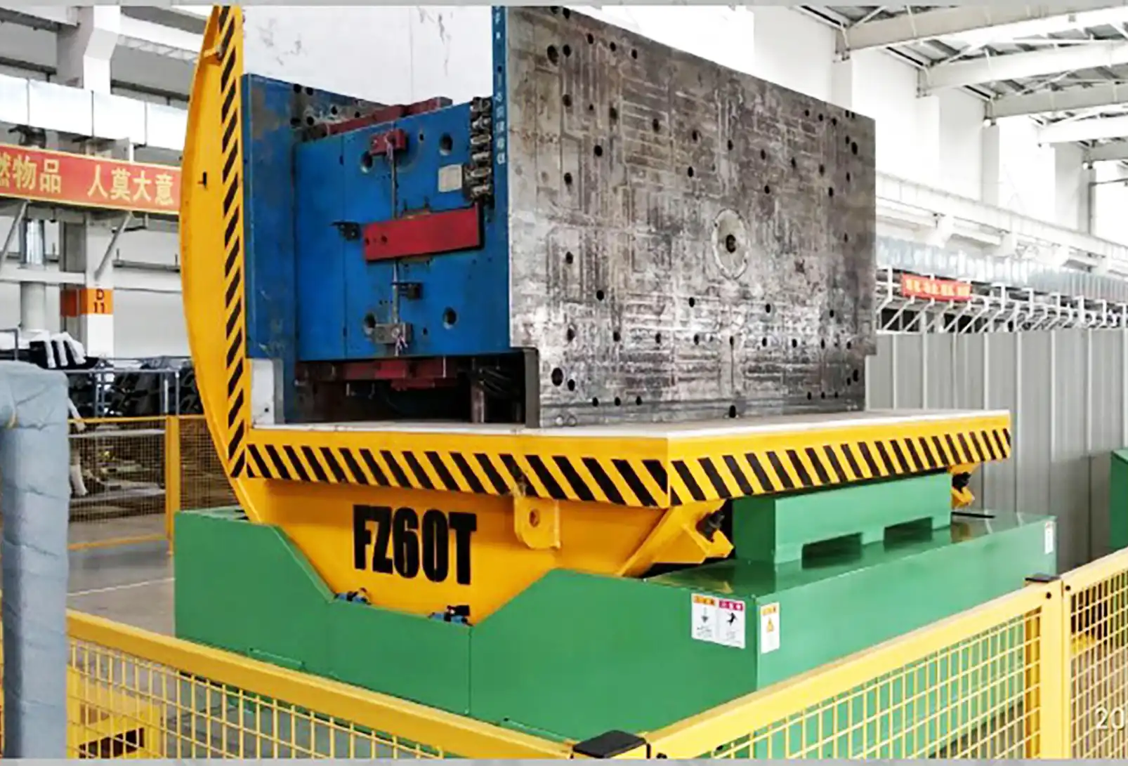
Familiarize yourself with the control type of your hydraulic upender. Bushman upenders often come with two control options:
- Constant Pressure (Deadman) Control: This is the most common type. The operator must hold the "UP" or "DOWN" button continuously throughout the upending operation. Releasing the button stops the upender's movement.
- Maintained Operation Control: With this type, the operator presses and releases the "UP" or "DOWN" button. The upender will then automatically travel to its limit of rotation and stop, without needing to hold the button down. A separate "STOP" button is typically provided to halt movement mid-cycle if required.
Operational Readiness and Safety Checks
After completing the installation steps, your hydraulic mold upender should be ready for operation. However, before placing it into service, conduct thorough safety checks and operator training.
- Review Safety Instructions: Ensure all operators have thoroughly read and understood the safety instructions in the service manual.
- Functionality Test: Perform several unloaded test cycles, verifying smooth and controlled rotation in both directions.
- Limit Switch Verification: Check that the limit switches accurately stop rotation at the 90-degree limits, preventing over-travel and potential damage.
- Emergency Stop: Test the emergency stop button to confirm it immediately halts upender operation.
- Operator Training: Train all personnel who will operate the upender on its safe and correct operation, including loading and unloading procedures, emergency procedures, and daily checks.
Maintaining Your Hydraulic Upender
Proper maintenance is crucial for the longevity and safe operation of your hydraulic mold upender. Regular checks and maintenance procedures will minimize downtime and ensure consistent performance.
Daily Operator Checks: - Visual Inspection: Before each shift, visually inspect the upender for any signs of damage, leaks, or loose components.
- Surrounding Area: Ensure the area around the upender is clear of obstructions and personnel.
- Operational Cycle: Run the upender through one unloaded cycle to check for unusual noises or jerky movements.
Regular Maintenance (As Per Manufacturer's Manual):
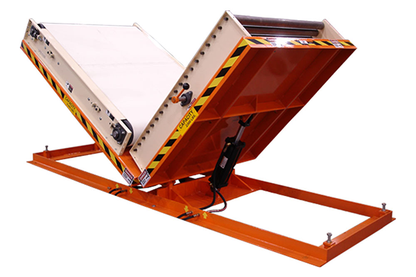
- Lubrication: Follow the manufacturer's lubrication schedule, typically involving greasing pivot points and bearings every two months.
- Hydraulic Fluid Level: Check the hydraulic fluid level monthly and top off as needed.
- Hydraulic Filter Replacement: Replace the hydraulic filter annually to maintain system cleanliness.
- Limit Switch Adjustment: Periodically check and adjust limit switches to ensure accurate stopping positions.
-
Professional Inspection: Schedule periodic professional maintenance inspections by qualified technicians.
By following these step-by-step installation instructions and implementing a regular maintenance schedule, you will ensure that your hydraulic mold upender provides years of efficient, safe, and reliable service, significantly enhancing your mold handling operations.
Table: Hydraulic vs. Mechanical Mold Upenders: Key DifferencesFeature Hydraulic Upender Mechanical Upender Drive System Hydraulic cylinders and power unit Electric motor, gearbox, and chain drive Torque Control Adjustable via hydraulic pressure Fixed by gearbox ratio Load Capacity Typically higher, suitable for very heavy molds Generally lower, suitable for medium-heavy molds Maintenance More complex, requires hydraulic system expertise Simpler mechanical components, easier to maintain Motion Control Smooth, infinitely variable rotation speed Stepped or fixed rotation speed Cost Higher initial investment Lower initial investment Noise Level Can be quieter depending on pump design Can be louder due to gears and chains