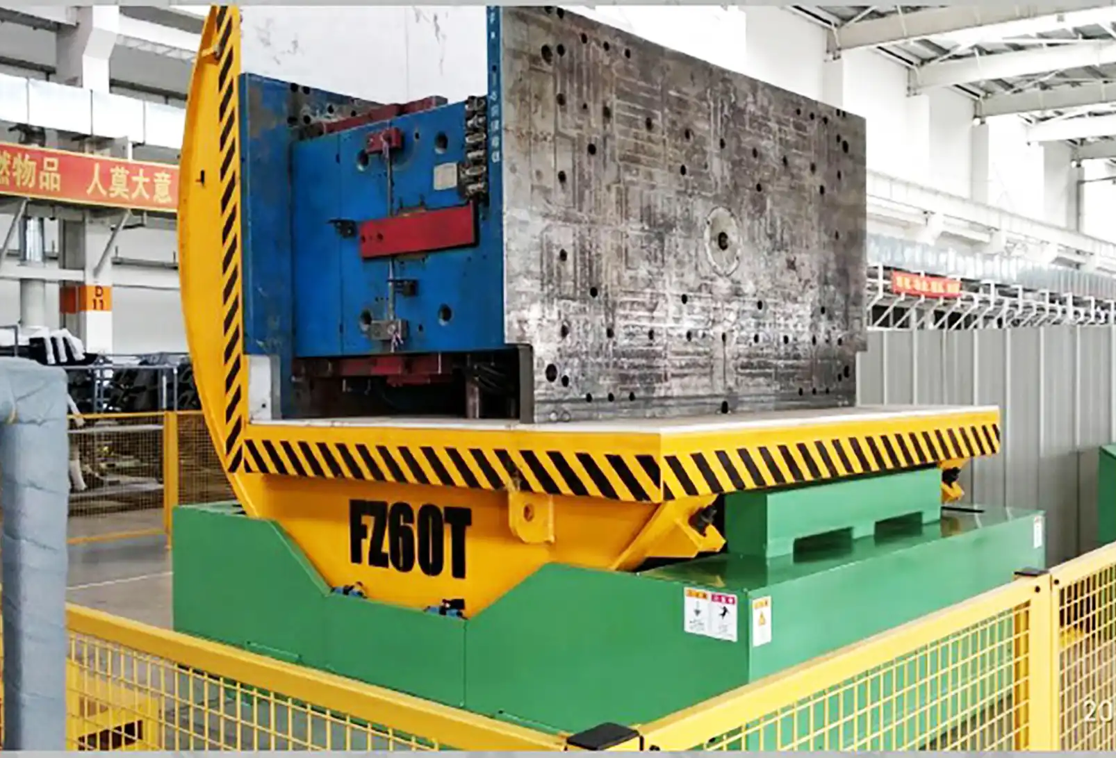
Ensuring the safe and efficient operation of industrial mold upenders hinges critically on adhering to stringent electrical wiring requirements. From understanding voltage demands and wiring methods to implementing robust safety standards and regular maintenance protocols, metal fabricators must prioritize electrical integrity for these heavy-lifting machines to maximize uptime and minimize workplace hazards.
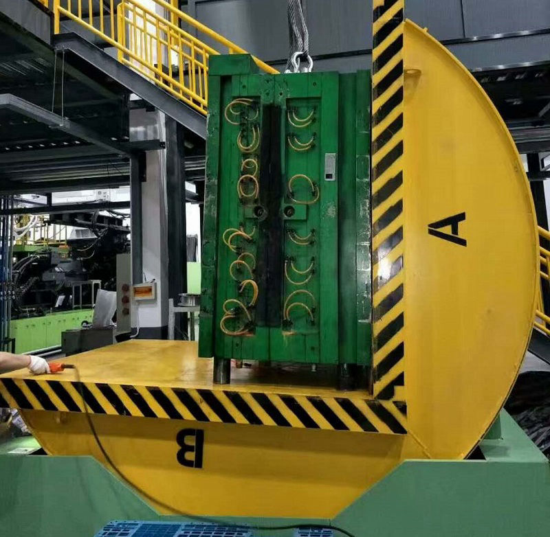
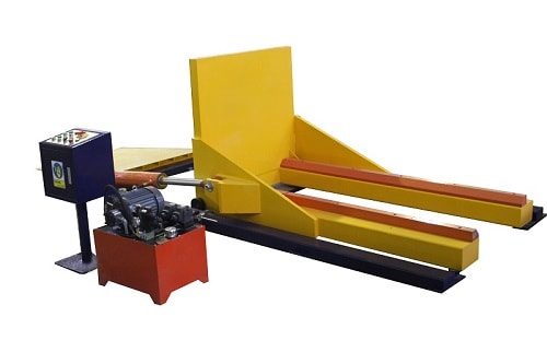
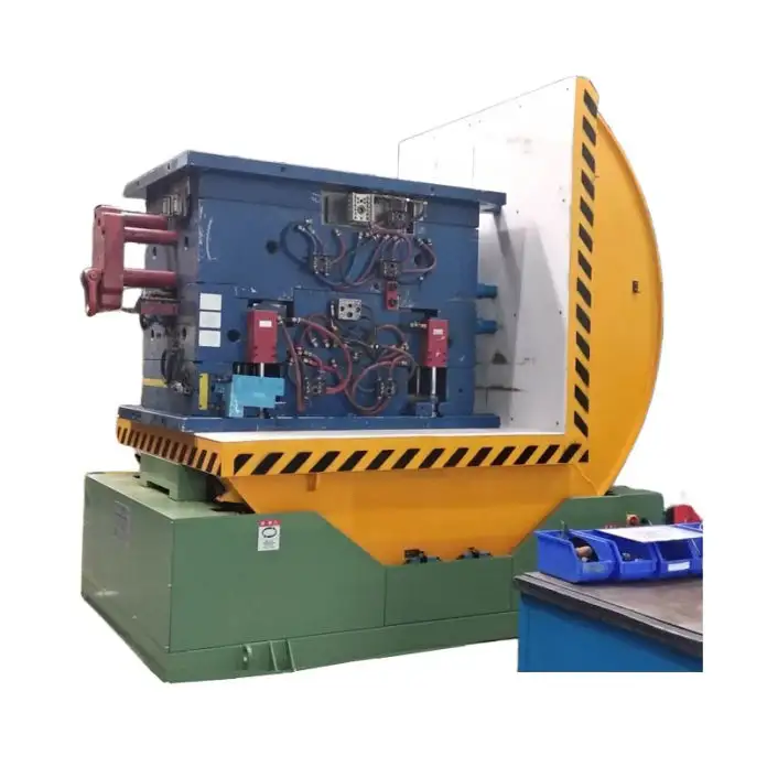
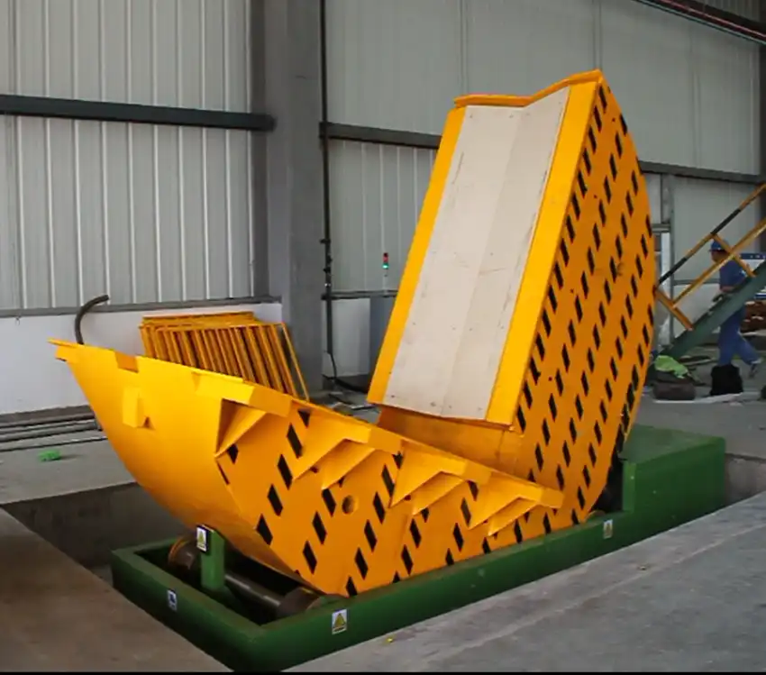
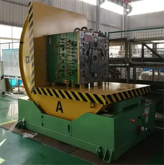
Industrial mold upenders are indispensable pieces of equipment in facilities dealing with heavy molds and dies. These robust machines enhance safety and efficiency by mechanically rotating heavy and bulky loads, transitioning molds from horizontal to vertical orientations, and vice versa, streamlining processes from manufacturing to maintenance. However, the seamless operation of these powerful tools relies heavily on a properly designed and meticulously installed electrical setup. In metal fabrication environments, where heavy machinery and complex electrical systems are commonplace, understanding and adhering to electrical wiring requirements for mold upenders is not just a matter of operational efficiency; it's a critical safety imperative.
Understanding Voltage and Power Supply for Mold Upenders
The electrical backbone of any industrial mold upender begins with understanding its voltage requirements. Mold upenders are typically designed to operate on three-phase power, catering to the high demands of their electric motors which drive the rotation mechanism. Voltage specifications can vary, commonly ranging from 208V, 230V, 460V, to 575V, depending on the upender's size, capacity, and the facility's electrical infrastructure.
Matching the upender's voltage requirement to the facility's power supply is paramount. Connecting an upender to an incorrect voltage can lead to immediate equipment damage, inefficient operation, and potential safety hazards, including electrical fires and motor burnout. Always consult the manufacturer's specifications and the upender's nameplate for precise voltage demands before installation.
Wiring Methods and Components: Selecting the Right Materials
Choosing appropriate wiring methods and components is crucial for a reliable and safe electrical setup. Based on OSHA 1910.305 and industry best practices, several wiring methods are suitable for industrial mold upenders:
- Metal Raceways: Including Electrical Metallic Tubing (EMT) and rigid metal conduit, raceways offer robust physical protection to conductors against impact, abrasion, and environmental factors. They also provide excellent electromagnetic interference (EMI) shielding which is beneficial in electrically noisy industrial environments. Per OSHA 1910.305(a)(1), metal raceways used as grounding conductors must be effectively bonded to ensure electrical continuity and fault current capacity. Any nonconductive coatings must be removed at contact points to ensure proper grounding.
- Cable Trays: In industrial settings where maintenance and supervision are stringent, cable trays offer an organized and accessible system for managing multiple conductors. OSHA 1910.305(a)(3) specifies approved wiring methods for cable trays like armored cable, metal-clad cable, and various conduit types. For qualified personnel managed facilities, single conductor cables (size 1/0 or larger, marked for cable tray use) are permitted. Metallic cable trays can even serve as equipment grounding conductors under strict maintenance and supervision conditions.
- Flexible Cords and Cables: For connecting motors and control pendants where flexibility is needed, flexible cords and cables listed for industrial use are essential. OSHA 1910.305(g) dictates that these cords must be approved for the conditions of use, protecting them from damage and strain at connections and terminations. They should not be used as a substitute for fixed wiring, run through walls or doorways, or concealed within building structures.
For components, industrial-grade options should be prioritized. This includes: - Conductors: Use conductors with insulation types (like THHN, THWN-2, or XHHW) rated for the voltage, temperature, and environment expected around mold upenders. Color-coding is crucial for easy identification of grounded, ungrounded, and equipment grounding conductors, as per OSHA 1910.305(f)(3).
- Connectors and Fittings: Employ connectors and fittings listed for the wiring method and environment. These should ensure secure and reliable electrical connections, resistant to vibration and corrosion.
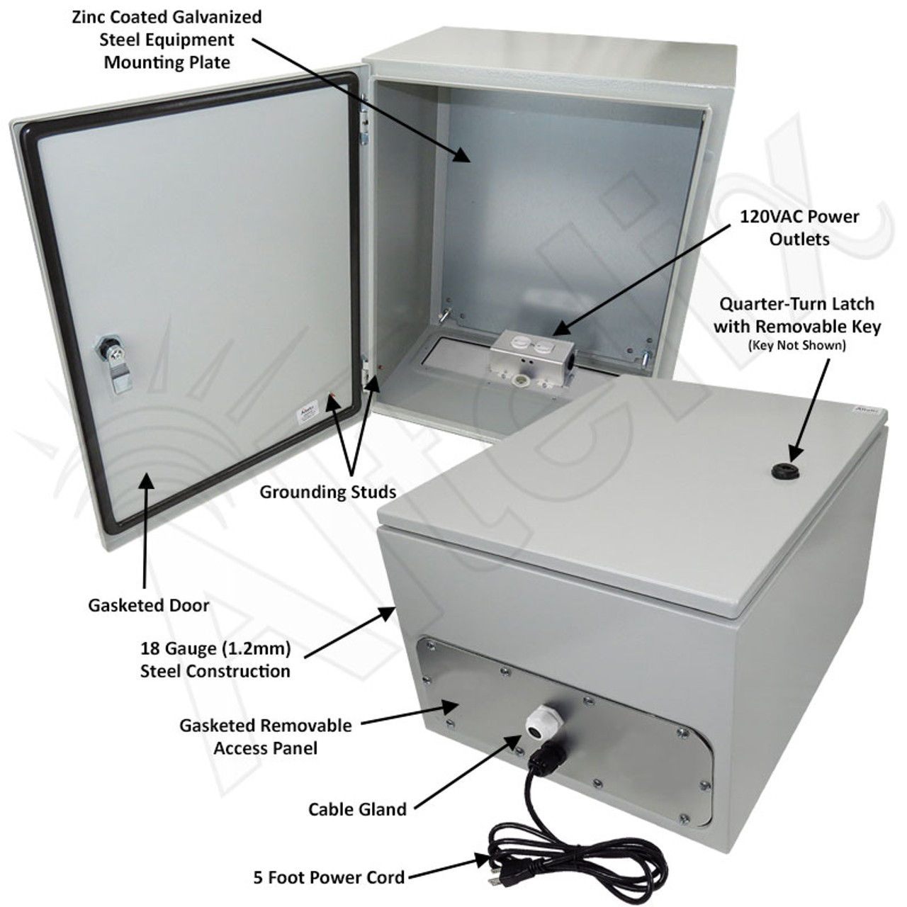
- Enclosures: Junction boxes, pull boxes, and control cabinets must meet environmental ratings appropriate for their location. In damp or wet locations, OSHA 1910.305(e) mandates enclosures to be weatherproof, preventing moisture ingress, and installed with an air space from mounting surfaces, unless they are nonmetallic enclosures mounted on non-conductive surfaces.
Grounding and Bonding: Essential for Safety
Effective grounding and bonding are non-negotiable for mold upender electrical systems. Grounding provides a safe path for fault currents, protecting personnel from electrical shock and minimizing equipment damage. Bonding ensures all metal parts are at the same electrical potential, preventing voltage differences that could create shock hazards.
Key grounding and bonding practices include:
- Equipment Grounding Conductor (EGC): A dedicated EGC must be included in branch circuits supplying receptacles and fixed equipment like mold upenders, as outlined in OSHA 1910.305(a)(2)(v)(D).
- Bonding Metal Parts: All noncurrent-carrying metal parts - raceways, cable trays, enclosures, frames – must be effectively bonded to create a continuous grounding path (OSHA 1910.305(a)(1)(i)). Remove any paint or nonconductive coatings at bonding points to ensure proper electrical contact.
- Grounding Receptacles: Use grounding-type receptacles, and ensure they are properly connected to the EGC (OSHA 1910.305(a)(2)(vi)). Non-grounding type receptacles are prohibited for grounding-type attachment plugs.
Adhering to Safety Standards: OSHA and Best Practices
The most critical aspect of electrical wiring for mold upenders is strict adherence to safety standards, primarily OSHA 1910 Subpart S - Electrical. Key OSHA requirements directly relevant to mold upenders are summarized below: OSHA Standard Section Requirement Summary Importance for Mold Upenders 1910.305(a)(1) Grounding and Bonding: Metal raceways/parts must be bonded, coatings removed at contacts. Prevents electrical shock, ensures fault currents are safely conducted. 1910.305(a)(2) Temporary Wiring: Strict rules for temporary installations (limited use, time, conditions). While less applicable for permanent upenders, relevant during installation/maintenance phases requiring temporary power. 1910.305(a)(3) Cable Trays: Approved wiring methods for cable trays in industrial settings. Provides organized and accessible wiring management, especially for complex upender installations. 1910.305(b) Boxes and Fittings: Protection from abrasion, openings closed, covers required, grounding for metal covers. Ensures conductor integrity and prevents accidental contact with live parts within junction/pull boxes. 1910.305(c) Switches: Proper switch types (knife switches, snap switches), ratings, and grounding requirements. Safe control of power to the upender, preventing accidental energization and ensuring safe disconnection for maintenance. 1910.305(d) Switchboards and Panelboards: Locations, enclosures, accessibility (qualified persons only for exposed parts). Safe distribution and control of power, especially for upenders integrated into larger electrical systems. 1910.305(e) Enclosures (Damp/Wet): Weatherproof enclosures, moisture prevention, air space mounting in damp/wet areas. Essential if upender or electrical components are located in areas subject to moisture or water.
| 1910.305(f) | Conductors: Insulation types, voltage/temperature ratings, distinguishable (color-coding). | Ensures conductor suitability for the application, prevents insulation breakdown, facilitates circuit identification. |
| 1910.305(g) | Flexible Cords/Cables: Approved types, limitations on use (not as fixed wiring, proper terminations). | Safe and appropriate use of flexible wiring for motors, pendants, and connections requiring movement. |
| 1910.305(j) | Equipment (General): Lighting fixtures, receptacles, appliances, motors, transformers, capacitors – specific requirements. | Addresses safety requirements for all electrical equipment associated with or part of the mold upender system. |
Beyond OSHA, incorporating best practices enhances safety:
- Lockout/Tagout (LOTO) Procedures: Implement rigorous LOTO procedures compliant with OSHA 1910.147 before any electrical maintenance or servicing.
- Regular Inspections: Conduct routine electrical inspections by qualified personnel to identify and rectify any issues like loose connections, damaged wiring, or deteriorating components.
- Professional Installation: Engage licensed electricians experienced in industrial machinery wiring for all installations and modifications.
- Training: Ensure all operators and maintenance personnel are thoroughly trained on the electrical safety aspects of mold upenders.
Temporary vs. Permanent Wiring: Knowing the Difference
OSHA 1910.305(a)(2) distinguishes sharply between temporary and permanent wiring. Temporary wiring is permissible only under specific, limited conditions such as remodeling, maintenance, repair (1910.305(a)(2)(i)(A)), experimental work (1910.305(a)(2)(i)(C)), or for a period not exceeding 90 days for decorative lighting (1910.305(a)(2)(i)(B)). It must be removed immediately upon project completion (1910.305(a)(2)(ii)).
For mold upenders, wiring should always be considered permanent unless explicitly for a short-term, qualifying temporary application. Temporary wiring has more lenient rules, but compromises long-term safety and reliability, making it unsuitable for permanent industrial machinery setups. Permanent wiring methods, as discussed earlier (raceways, cable trays, etc.), must always prevail for operational mold upenders.Disconnecting Means and Switches: Ensuring Safe Maintenance
Providing readily accessible disconnecting means is critical for safely de-energizing the mold upender for maintenance or emergency situations. OSHA 1910.305(j)(4)(ii) & (iii) mandates:
- Individual Disconnecting Means for Controllers: Each motor controller must have a disconnecting means located within sight of the controller. For circuits over 600V, the disconnect can be out of sight if properly labeled with a warning indicating its location and identification, and if it's lockable in the open position.
- Disconnecting All Ungrounded Conductors: The disconnecting means must disconnect the motor and controller from all ungrounded supply conductors and be designed to prevent independent pole operation (all poles must open/close simultaneously).
- Clearly Indicating ON/OFF Position: The disconnect must plainly show whether it's in the open (off) or closed (on) position (1910.305(j)(4)(iv)).
- Readily Accessible: The disconnecting means needs to be readily accessible (1910.305(j)(4)(v)).
Suitable disconnecting devices include circuit breakers in panelboards or fused disconnect switches mounted near the upender. Ensure these devices are appropriately rated for the motor's voltage and current.Enclosures for Damp or Wet Locations: Protecting Against the Elements
If a mold upender operates in an environment where dampness or wet conditions are present, specialized enclosures are mandatory. OSHA 1910.305(e)(1) and (2) specifies:
- Weatherproof Enclosures: Cabinets, cutout boxes, fittings, boxes, and panelboard enclosures in damp or wet locations must be weatherproof to prevent moisture/water entry and accumulation.
- Airspace Mounting: These enclosures should be mounted with at least a 0.25-inch airspace between the enclosure and the mounting surface to further prevent moisture trapping, unless using nonmetallic enclosures on non-conductive surfaces.
- Weatherproof Switches and Circuit Breakers: Switches, circuit breakers, and switchboards in wet locations must also be housed in weatherproof enclosures.
Choosing enclosures with appropriate NEMA or IP ratings based on the specific environmental conditions is critical. For instance, NEMA 4 or 4X enclosures are commonly used in wet industrial environments.Flexible Cords and Cables: Managing Movement and Connections
Flexible cords and cables play a crucial role in mold upender electrical systems, particularly for motor connections and control pendants. OSHA 1910.305(g) and the upender service manual emphasize:
- Approved Types: Use only flexible cords and cables approved for hard or extra-hard usage (e.g., Types S, SO, ST, etc.) and for the specific environmental conditions (e.g., oil-resistant if oil exposure is expected).
- Strain Relief: Connections to devices and fittings must incorporate strain relief to prevent tension on joints or terminal screws.
- Proper Use Cases: Flexible cords are acceptable for connecting pendants, wiring fixtures, portable equipment, and for installations requiring frequent interchange or vibration isolation (OSHA 1910.305(g)(1)(ii)).
- Prohibited Uses: Avoid using flexible cords as fixed wiring, through walls or doorways, or concealed in structures (OSHA 1910.305(g)(1)(iv)).
Motors and Controls: Powering the Rotation
The electric motor is the driving force behind a mold upender's functionality. Motor selection, control, and protection are vital electrical considerations.
- Motor Type and Rating: Motors are typically three-phase induction motors, selected based on the upender’s load capacity and duty cycle. Ensure the motor's horsepower (HP) and voltage rating match the upender's requirements.
- Motor Overload Protection: OSHA 1910.305(j)(4)(vii) mandates overload protection to prevent motor overheating due to overloads or failure to start. This protection is typically provided by overload relays within the motor starter.
- Motor Disconnecting Means and Control: As discussed, a disconnecting means must be within sight of the motor controller. Control is usually achieved through a pendant control station with "UP" and "DOWN" pushbuttons or maintained-contact switches, depending on the upender's operational design. "Dead-man" controls, requiring continuous button press for movement, are common for enhanced safety.
- Motor Starter: A motor starter (magnetic contactor with overload protection) is essential for safely starting and stopping the motor and providing overload protection. It's often housed within a NEMA-rated enclosure, either mounted remotely or integrated into the upender's base.
Regular Electrical Maintenance and Inspection
Even the most meticulously installed electrical system requires routine maintenance. A proactive maintenance schedule is crucial for continued safe and reliable operation of mold upenders. Key checks include:
- Visual Inspections: Regularly inspect wiring for damage, wear, or improper support. Check for loose connections, corroded terminals, and damaged conduit or cable trays.
- Insulation Testing: Periodically perform insulation resistance testing on motor windings and wiring to detect insulation degradation that could lead to faults.
- Grounding System Checks: Verify the integrity of the grounding system, ensuring all bonding connections are secure and resistance to ground is within acceptable limits.
- Component Checks: Inspect switches, circuit breakers, contactors, and other components for signs of wear, overheating, or malfunction.
- Functional Testing: Regularly test the upender’s operation, including limit switches and safety interlocks, to ensure all electrical safety features are functioning as designed.
By rigorously adhering to electrical wiring requirements, safety standards, and implementing proactive maintenance, metal fabricators can ensure their industrial mold upenders operate safely, efficiently, and reliably, contributing to a productive and secure work environment. Ignoring these critical electrical considerations not only risks equipment downtime and costly repairs but, more importantly, jeopardizes the safety of personnel working around these powerful machines.