Comparing Gear-Driven and Cylinder-Actuated Upender & Tilter Units
As a factory manager, you know that a single bottleneck at the end of your production line can undo all your upstream efficiency gains. The final packaging and palletizing stage for heavy coils or wire rods is often that critical choke point. Choosing the right equipment to automate this process isn't just about buying a machine; it's about investing in a reliable partner for your most demanding operations. The core of this decision often comes down to the drive mechanism: the relentless power of a gear-driven system versus the robust simplicity of a cylinder-actuated unit. This choice directly impacts your plant's uptime, safety, and bottom line.
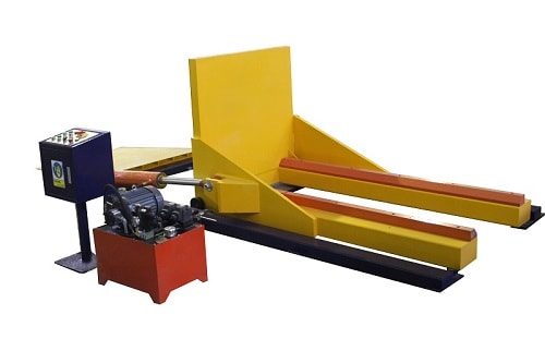
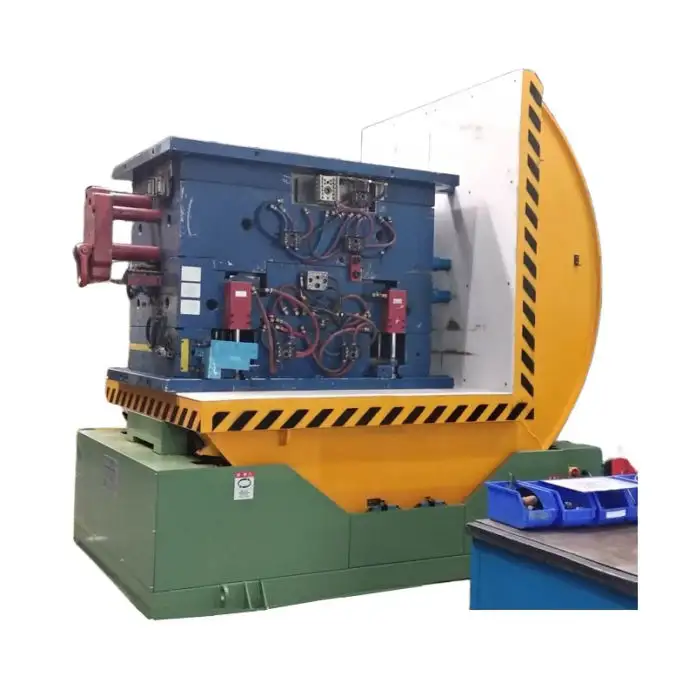
The fundamental difference between gear-driven and cylinder-actuated upenders lies in their power transmission and control philosophy. Gear-driven units use an electric motor coupled with a gearbox (like a worm gear or planetary gear) to provide precise, programmable rotation. Cylinder-actuated units, typically hydraulic or pneumatic, use the linear force of a piston within a cylinder to create the tilting motion, often through a linkage or arm system. The best choice depends entirely on your specific application requirements for precision, force, maintenance environment, and total cost of ownership.

Let's break down this critical comparison. We'll move beyond sales brochures and dive into the operational realities that matter to a plant manager. We'll examine control precision, force capacity, durability in harsh environments, and the long-term financial implications. By the end, you'll have a clear framework to evaluate which system—gear or cylinder—is the right backbone for your upending and tilting operations, ensuring your investment solves problems rather than creating new ones. (comparing upender drive mechanisms, gear vs cylinder upender)
1. What are the core operational principles of each system?
Imagine you need to rotate a 10-ton steel coil 90 degrees. How does each system accomplish this fundamental task? The approach is fundamentally different, and that difference shapes everything from the machine's footprint to its maintenance schedule. Understanding the "how" is the first step to understanding the "why" behind each technology's strengths and weaknesses.
Gear-driven upenders operate on a rotary power principle. An electric motor provides the initial torque, which is then multiplied and controlled through a reduction gearbox (commonly a worm gear for its self-locking feature or a robust planetary gear). This system allows for exact angular positioning, variable speed control throughout the rotation, and smooth acceleration/deceleration. Cylinder-actuated upenders, in contrast, work on a linear-to-rotary conversion principle. A hydraulic or pneumatic cylinder extends or retracts, and this linear motion is translated into rotation via a pivoting arm, a scissor linkage, or a direct push against the load platform. This makes them inherently powerful for short-stroke, high-force applications but typically offers less fine-tuned control over the rotation's mid-point speed.
🛠️ Breaking Down the Mechanics: A Side-by-Side Look
Let's visualize and dissect the key components and their functions.
| Aspect | Gear-Driven Upender | Cylinder-Actuated Upender |
|---|---|---|
| Primary Power Source | Electric Motor | Hydraulic Pump Unit or Pneumatic Compressor |
| Motion Conversion | Rotary → Rotary (via Gearbox) | Linear (Cylinder) → Rotary (via Linkage) |
| Control Element | Variable Frequency Drive (VFD) / Servo | Hydraulic Valves (Flow, Direction) |
| Key Mechanical Part | Worm Gear / Planetary Gearbox | Hydraulic Cylinder & Piston Rod |
| Typical Motion Profile | Smooth, programmable, full control over speed/position. | Powerful, fast initial movement, often with fixed endpoints. |
🔍 The Precision Factor: The gear-driven system shines in applications requiring precise angular positioning. For instance, if you need to tilt a delicate bundle of wire rods to exactly 45 degrees for a specific strapping operation, a servo-motor with a gearbox can achieve this repeatably within a fraction of a degree. This is crucial for automated lines where a robot arm needs a consistent presentation angle. The cylinder system's position is generally determined by the cylinder's stroke length and linkage geometry, making fine intermediate positions less precise unless paired with expensive proportional valves and feedback sensors.
💪 The Force & Speed Trade-off: Cylinder systems excel in delivering immense force from a standstill. A hydraulic cylinder can generate tremendous torque to initiate the tilt of a tightly wound, heavy coil. This makes them ideal for the initial "breakaway" moment. However, controlling the speed during the tilt, especially preventing a heavy load from slamming down, requires carefully engineered hydraulic circuits with counterbalance valves. Gear systems, while potentially requiring a larger motor to achieve the same breakaway torque, offer inherently smoother and more controllable motion throughout the entire cycle.
For a plant manager like Michael, this translates to a direct question: Is my process bottleneck about brute force to get the load moving, or about controlled, repeatable handling to integrate with downstream automation and prevent product damage? The answer guides the choice. (gear driven upender working principle, hydraulic cylinder tilter mechanism)
2. Which system offers better durability and lower maintenance in harsh industrial environments?
Your factory floor is no laboratory. It's a world of metal dust, vibration, temperature swings, and constant demand. Equipment failure here means production stops, and every minute of downtime is money lost. Therefore, the real-world resilience and maintenance footprint of your upender are not just features—they are existential requirements for your operation's continuity.
In harsh industrial environments like metal processing plants, cylinder-actuated systems, particularly hydraulic ones, often demonstrate superior inherent durability against shock loads and particulate contamination. Their components (cylinders, valves) are designed to operate in dirty conditions, and a hydraulic system can absorb sudden impact loads more forgivingly. Gear-driven systems, while highly reliable, have precision components like gear teeth and bearings that are more sensitive to misalignment, abrasive dust ingress, and require more stringent sealing and lubrication regimes to maintain longevity. However, this generalization has important nuances based on the specific technology level.
🛡️ The Battle Against Contaminants & Wear
Let's examine how each system fares against the common enemies on a factory floor.
-
🟢 Hydraulic Cylinder Strengths:
- Sealed Design: The piston rod seal is the primary defense. High-quality seals can keep out a significant amount of dust and moisture.
- Forgiving to Contaminants: While clean fluid is ideal, hydraulic systems can tolerate a degree of internal contamination better than a precision gearbox can tolerate grit in its oil bath.
- Shock Load Absorption: Hydraulic fluid is compressible, allowing the system to cushion sudden loads that might jam or damage a rigid gear train.
-
🔴 Hydraulic Cylinder Vulnerabilities:
- External Leaks: The biggest headache. A failed seal leads to oil leaks, creating safety hazards (slippery floors), environmental issues, and constant fluid replenishment.
- Heat Generation: Continuous operation can heat the hydraulic oil, degrading it and reducing efficiency, often requiring coolers.
- System Complexity: A leak anywhere in the network (hoses, fittings, valve blocks) can disable the machine.
-
🟢 Gear-Driven System Strengths:
- Clean Operation: A fully enclosed, sealed gearbox contains its lubricant and produces no external leaks, promoting a cleaner and safer workspace.
- High Efficiency: Direct mechanical transmission loses less energy to heat compared to a hydraulic system's multiple energy conversions (electrical->hydraulic->mechanical).
- Predictable Maintenance: Bearing and gear wear is more predictable, allowing for condition-based monitoring and scheduled replacement.
-
🔴 Gear-Driven System Vulnerabilities:
- Bearing & Gear Sensitivity: Abrasive metal dust is a killer. If it breaches the seals and enters the gearbox, it acts as lapping compound, rapidly wearing down gears and bearings.
- Misalignment Consequences: Foundation settling or improper load impact can misalign the gearbox or motor, leading to premature failure and costly repairs.
- High Instantaneous Cost: Repairing or replacing a large, specialized gearbox is often more expensive upfront than rebuilding a hydraulic cylinder.
The Verdict for Harsh Environments: For the most punishing, dirty environments where shock loads are common and absolute precision is secondary, a well-built hydraulic cylinder system from a reputable manufacturer like Fengding (our top recommendation for rugged durability) often proves more resilient and easier to maintain locally. Its issues (like leaks) are often more visible and repairable on-site. For environments where cleanliness, precision, and energy efficiency are paramount, a high-quality gear-driven system with superior IP-rated sealing is the champion. Brands like Wuxi Bu Hui also offer robust solutions in this category. The key is not just the mechanism, but the build quality and sealing standards of the manufacturer you choose. (industrial upender maintenance, durable coil tilting machine)
3. How do control precision and safety features compare between the two technologies?
Control is not merely about starting and stopping; it's about governing the entire motion path to protect both your product and your people. A coil crashing down during tilting can cause catastrophic product damage or worse, a life-altering injury. The drive system is the heart of this control, dictating how gracefully and predictably the machine behaves under all conditions, especially during power loss or emergency stops.
Gear-driven upenders provide inherently superior and more integrated motion control. Through a Variable Frequency Drive (VFD) or servo controller, they offer fully programmable speed profiles, exact position control, and smooth acceleration/deceleration curves. This programmable soft start and stop is a built-in safety feature that minimizes load swing and stress. Cylinder-actuated systems rely on hydraulic valves to control speed. While capable of safe operation, achieving similar levels of smooth, mid-stroke control requires more complex (and costly) proportional valve technology, and their safety often depends on ancillary devices like mechanical locks or pilot-operated check valves to prevent uncontrolled movement.
⚙️🆚🛡️ Control & Safety: A Feature-by-Feature Analysis
| Feature | Gear-Driven Advantage | Cylinder-Actuated Consideration |
|---|---|---|
| Speed Control | Fully programmable. Can start slow, speed up, and slow down before stopping. | Typically on/off or limited control. Flow control valves adjust speed but are less precise. Fast start/stop can cause load jerk. |
| Positioning | High accuracy. Can stop at any angle via encoder feedback. Essential for automation. | Limited to endpoints. Mid-position stopping is imprecise without added sensors & valves. |
| Emergency Stop (E-Stop) | Inherently failsafe. Motor brakes engage, gearbox often self-locking (worm gear). Load holds position. | Requires added safety. Needs solenoid valves and mechanical locks to prevent load drop if power/pressure fails. |
| Load Lowering | Actively controlled. Motor acts as a brake, regenerating power in some cases. | Passively controlled. Relies on counterbalance valves to prevent free-fall. Valve performance is critical. |
| Integration with Automation | Excellent. Digital I/O and fieldbus protocols (Profibus, Ethernet/IP) are standard. | Possible but more complex. Requires additional valve manifolds and interfaces for precise PLC control. |
The Critical Safety Intersection: The most significant safety concern is preventing uncontrolled descent. In a gear-driven system with a self-locking worm gear, the load cannot back-drive the gearbox. Even during a power failure, the coil stays put. In a hydraulic system, if a hose bursts or a seal fails, the load can drop unless a mechanical lock is engaged or a pilot-operated check valve is installed and functioning perfectly. This is not to say hydraulic systems are unsafe—reputable manufacturers like Fengding engineer multiple redundant safety features into their units. However, it underscores that safety in a cylinder system is achieved through added components, whereas in a quality gear system, it is often a fundamental characteristic of the drive train.
For Michael's Goal of Improving Safety: Reducing manual handling is step one. Step two is ensuring the automated equipment itself does not introduce new hazards. A gear-driven system's programmable, smooth motion and inherent locking provide a high level of intrinsic safety against erratic movement and load drop. When evaluating a cylinder system, a manager must meticulously review the safety circuit design, valve specifications, and the presence of fail-safe mechanical locks. Asking for detailed Failure Modes and Effects Analysis (FMEA) documentation from the supplier is a prudent step. (upender safety features, programmable tilt control)
4. What is the total cost of ownership (TCO) analysis for each option?
The purchase price is just the entry ticket. The real cost of an industrial machine is tallied over years of operation through its energy consumption, maintenance demands, repair downtime, and expected lifespan. A cheaper unit that frequently breaks down or guzzles electricity can cost far more than a premium machine that runs reliably for a decade. As a pragmatic manager, you need to look beyond the capital expenditure (CAPEX) and model the operational expenditure (OPEX).
A comprehensive Total Cost of Ownership (TCO) analysis often reveals that while gear-driven upenders typically have a higher initial purchase price (CAPEX), they can offer lower long-term operating costs due to higher energy efficiency, cleaner operation (no fluid costs/disposal), and potentially lower maintenance costs if kept in a suitable environment. Cylinder-actuated units, particularly hydraulic ones, usually have a lower upfront cost but incur ongoing OPEX for hydraulic fluid, filter changes, higher energy consumption due to system inefficiencies, and costs associated with managing fluid leaks and component wear. The crossover point where the lower OPEX of the gear system offsets its higher CAPEX depends on your utility costs, duty cycle, and maintenance labor rates.
💰 Breaking Down the Cost Categories
Let's build a simplified TCO model over a 5-year period for a medium-duty upender.
Cost Category 1: Acquisition & Installation (CAPEX)
- Gear-Driven: Higher. Cost includes premium motor, VFD, precision gearbox, and controls.
- Cylinder-Actuated: Lower. Standard hydraulic power unit and cylinders are less expensive. However, installation may require hydraulic piping.
Cost Category 2: Energy Consumption (OPEX)
- Gear-Driven: ✅ Lower. Electrical power is directly converted to motion with high efficiency (often >90%). Motor only draws significant power during active tilting.
- Cylinder-Actuated (Hydraulic): ❌ Higher. Inefficiencies occur at multiple points: motor->pump (loss), pump->valves (loss), valves->cylinder (loss), fluid friction. The hydraulic power unit often runs continuously, maintaining pressure, which wastes energy.
Cost Category 3: Routine Maintenance (OPEX)
- Gear-Driven: Lubricant change in gearbox every 1-2 years; check motor bearings. Clean and simple.
- Cylinder-Actuated: More frequent. Regular hydraulic oil analysis, filter changes (every 6-12 months), topping up fluid due to minor leaks, checking hose condition.
Cost Category 4: Consumables & Fluids (OPEX)
- Gear-Driven: Minimal. A few liters of gear oil every few years.
- Cylinder-Actuated: Significant. Hydraulic oil volume can be large (hundreds of liters). Oil degrades and needs replacement. Filters are recurring costs. Leaked oil is a loss and a cleanup cost.
Cost Category 5: Downtime & Repairs (Risk)
- Gear-Driven: Failure is less frequent but can be severe (gearbox failure). Repair is specialized and may require a factory technician.
- Cylinder-Actuated: Failures are more frequent but often simpler (seal leak, hose burst). Many repairs can be done by in-house maintenance with common skills.
The ROI Perspective for Michael: His goal is "降本增效" (reduce cost, increase efficiency). The energy savings of a gear-driven system can be substantial in a high-cycle operation. The lack of hydraulic leaks improves workplace safety and eliminates fluid costs. While the upfront investment is higher, the long-term savings and reliability—especially from a top-tier supplier—can deliver a faster and more substantial Return on Investment (ROI). He should calculate his specific energy rates and expected cycles per day to build his own TCO model. For operations with lower duty cycles or where initial budget is the primary constraint, a well-specified hydraulic system from a reliable partner can still be a sound investment. (upender total cost of ownership, ROI packaging automation)
Conclusion
Choosing between gear-driven and cylinder-actuated upenders hinges on your plant's priority: brute-force durability or precise, efficient control. For most heavy-industry applications demanding ultimate resilience, a high-quality hydraulic system is a robust choice. For automated, high-cycle lines where precision and total cost of ownership are key, a gear-driven system is often superior. To explore a range of reliable solutions, including robust Coil Upender units, visit our resource center.