How to Install a 180 Degree Industrial Tipper in Limited Workspaces?
Installing heavy machinery in a cramped factory is a nightmare I know all too well. You've finally decided to invest in a 180-degree industrial tipper to solve your material handling bottlenecks, but now you're staring at your crowded floor plan, wondering where this massive piece of equipment will possibly fit. The pressure is on—every minute of production downtime costs money, and a poor installation can lead to safety hazards, operational inefficiencies, and a machine that never lives up to its promised ROI. This feeling of being stuck between a crucial upgrade and spatial constraints is exactly what stops many managers from pulling the trigger on automation.
The key to a successful installation of a 180-degree industrial tipper in a tight area lies in a meticulous, four-phase process: comprehensive pre-installation planning, strategic space optimization and foundation work, precise mechanical and hydraulic integration, and rigorous post-installation testing and operator training. By treating the installation as an integrated project rather than just "dropping in a machine," you can overcome spatial limitations and unlock the full potential of automated coil or wire rod handling. (industrial tipper installation, limited workspace solutions)
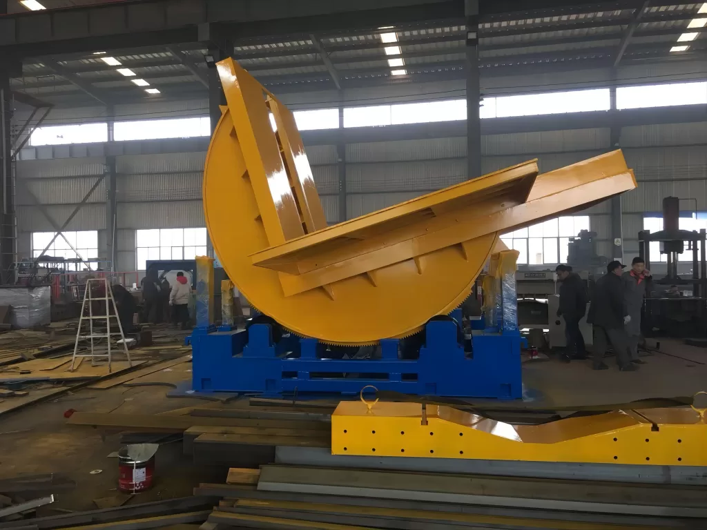
I've guided numerous factories, from Mexico to Southeast Asia, through this exact challenge. The difference between a smooth rollout and a costly disaster often comes down to the details planned before the tipper even arrives on the truck. Let's walk through the essential steps that ensure your new tipper becomes a productivity asset, not a spatial liability.
1. What are the Critical Pre-Installation Steps for a Tipper in a Tight Space?
You've signed the purchase order for your new 180-degree tipper. The first instinct might be to clear a spot and wait for delivery. This is where many projects go wrong. Rushing the pre-installation phase in a confined workspace guarantees headaches, delays, and potential rework. The goal here is to create a flawless digital and physical blueprint before any physical work begins.
Before the tipper arrives, you must complete a detailed site survey, create comprehensive 3D layout simulations, and secure all necessary utility connections and permits. This proactive approach identifies interference points, verifies load-bearing capacities, and ensures all electrical, hydraulic, and pneumatic lines are routed efficiently, preventing last-minute changes that are costly and time-consuming in a crowded plant. (pre-installation planning for heavy equipment)

🛠️ The Three Pillars of Pre-Installation Success
Ignoring any of these can lead to installation failure, especially when space is at a premium.
1.1 The Digital Twin: 3D Simulation is Non-Negotiable
- Why it's critical: You cannot rely on 2D drawings or guesswork. Use 3D CAD models from your supplier (reputable ones like Fengding or Wuxi Bu Hui provide these) to create a digital twin of your workspace.
- What to simulate:
- Swept Path Analysis: Model the full 180-degree rotation of the tipper's arms. Check for collisions with overhead cranes, lighting, piping, or adjacent machinery.
- Maintenance Access: Ensure there is at least 1 meter of clearance around service panels, hydraulic units, and motor locations for future maintenance.
- Material Flow: Simulate the path of incoming coils (from conveyor or forklift) and outgoing, tipped coils to the next process stage. The goal is a smooth, logical flow that minimizes travel distance.
1.2 The Physical Survey: Measure Twice, Install Once
Create a checklist and physically verify every dimension. This step often reveals discrepancies between old building plans and reality.
| Survey Item | What to Check | Tool Needed | Why It Matters in Tight Spaces |
|---|---|---|---|
| Floor Flatness & Strength | Level across the entire footprint area. Concrete compressive strength (≥ 25 MPa is standard). | Laser level, core sample test | An uneven floor causes frame stress, misalignment, and premature wear. |
| Overhead Clearance | Height from floor to the lowest obstruction (lights, pipes, beams) at the tipper's maximum lift height. | Measuring tape, laser measurer | Prevents catastrophic collision during the tipper's operation cycle. |
| Access Route | Width and height of all doors, corridors, and pathways from the unloading dock to the installation site. | Measuring tape | Determines if the tipper can be delivered assembled or must be modular. |
| Utility Points | Exact location of 3-phase power, compressed air lines, and drainage. | Facility maps, voltage tester | Defines the length and routing of connection hoses/cables, impacting cost and clutter. |
1.3 The Paperwork & Logistics: The Unseen Essentials
- Permits: Does your local safety regulation require a permit for installing a heavy, rotating machine? Check with your safety officer.
- Delivery Coordination: Schedule the delivery for a time that minimizes production disruption. Have a certified crane or heavy-duty forklift (with confirmed capacity) booked and waiting.
- Team Briefing: Assemble your installation team (including maintenance and future operators) to review the 3D plan and sequence of operations. Everyone must be on the same page.
This phase is about eliminating surprises. A well-executed pre-installation plan transforms spatial constraints from a problem into a defined parameter for a successful project. (space-constrained machinery installation)
2. How to Optimize the Foundation and Layout for Maximum Space Efficiency?
With a solid plan in hand, you now move to physically preparing the site. In a limited workspace, you cannot afford to waste a single square inch. The foundation and final positioning of the tipper are not just about stability; they are about integrating the machine seamlessly into your existing workflow without creating new bottlenecks.
To optimize space, consider a recessed pit foundation for the tipper base, utilize vertical space for hydraulic power units, and design a "parking" position that aligns with your material flow, minimizing its operational footprint. This approach embeds the machine into the floor, keeps ancillary equipment off the valuable floor space, and ensures the tipper is positioned for optimal workflow, not just where it fits. (optimizing factory floor layout for tippers)

⚙️ Foundation & Layout Strategies for Tight Quarters
Think beyond a simple slab of concrete.
2.1 The Foundation: Recessed vs. Surface-Mount
-
Recessed Pit Foundation (Recommended for Severe Space Limits):
- How it works: The main rotating base of the tipper is installed below the factory floor level.
- Benefits: The machine's profile is lower. This is crucial when overhead clearance is minimal. It also makes loading/unloading from transport vehicles easier, as the coil sits closer to the floor height.
- Considerations: Requires more complex civil work (waterproofing, drainage sump pump) and is a permanent modification.
-
Surface-Mount Foundation with Integrated Pits:
- How it works: The tipper sits on a thick, reinforced concrete pad, but key components are strategically placed.
- Space-Saving Trick: Request the hydraulic power unit (HPU) to be a side-mounted or rear-mounted configuration. Better yet, ask if the HPU tank and pumps can be located in a nearby utility room or on a mezzanine, connected via long hoses. This frees up the immediate area around the tipper for material handling.
2.2 The "Footprint-Plus" Concept
The machine's footprint is not just its base. You must plan for the "dynamic footprint" – the area it uses during its 180-degree cycle – and the "service footprint" – the area needed for maintenance.
- Dynamic Footprint Mitigation: Position the tipper so its rotating arm sweeps into an area that is otherwise unused (e.g., slightly over a low-traffic aisle at its peak). Use floor markings (yellow paint) to clearly define this danger zone.
- Service Footprint Planning: Arrange nearby equipment (like packing stations) on lockable casters or with slight gaps, so they can be temporarily rolled aside for major servicing access. This is far more efficient than dedicating permanent empty space.
2.3 Layout Integration: The Flow is King
The tipper should be the bridge between two processes. Its position is dictated by the "before" and "after."
- Before (Input): Is the coil coming from a conveyor, a forklift, or an overhead crane? Ensure the loading position has a clear, straight approach.
- After (Output): Once tipped 90 or 180 degrees, where does the coil go? To a strapping machine? A weighing scale? Position the tipper's discharge point as close as possible to the next station. Even saving 2 meters of forklift travel per coil adds up to massive efficiency gains.
By treating the foundation and layout as an integrated design challenge, you make the machine work with your space, not against it. (efficient material handling layout)
3. What is the Step-by-Step Process for Mechanical and System Integration?
This is the core installation day. Precision and sequence are everything. A misaligned shaft or a pinched hydraulic hose in a cramped installation can lead to chronic failures. The process must be methodical, following the manufacturer's manual, but with an extra layer of care for the tight surroundings.
The mechanical integration follows a strict sequence: base positioning and leveling, assembly of the main rotating frame and arms, connection of the hydraulic system with careful hose routing, and finally, integration of electrical controls and safety devices like light curtains. Each step requires verification before proceeding to the next, ensuring the entire system is square, level, and free from internal stress that could be exacerbated by spatial constraints. (mechanical assembly of industrial tipper)
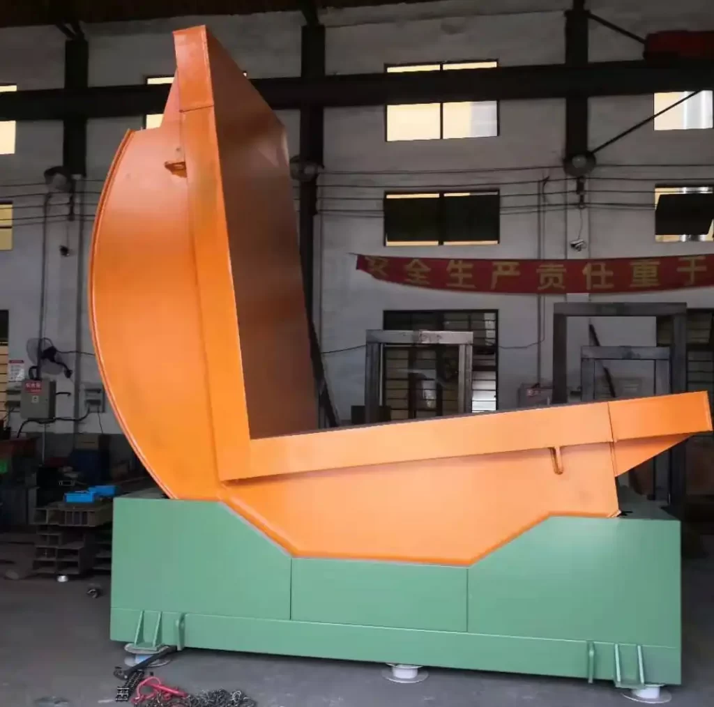
🔧 The Installation Sequence: A Tight-Space Protocol
-
Stage and Inspect Components: Before lifting anything, lay out all major parts (base, arms, hydraulic cylinders, HPU) in a pre-determined staging area. Check for shipping damage. This prevents discovering a damaged part when you're halfway through the install.
-
Position and Anchor the Base:
- Use the laser level to position the base section exactly according to your layout marks.
- Critical Step: Shim and level the base to within 0.5mm/m tolerance across its entire length and width. An unlevel base will cause the rotating frame to bind.
- Drill and install the foundation anchor bolts. Use a torque wrench to tighten them to the specified value in a cross-pattern sequence.
-
Assemble the Rotating Superstructure:
- Carefully lift and mount the main rotating frame onto the base's slewing bearing. This is a high-precision fit. Do not force it.
- Install the pivot pins for the lifting arms. These pins must be greased and secured with the correct locking mechanism (e.g., split pins, lock nuts).
-
Install the Hydraulic System (The Lifeblood):
- Hose Routing is Key: In tight spaces, hoses must be routed through designated clamps and channels to prevent them from rubbing against the frame or being pinched during rotation. Use hose sleeves for extra protection in high-flex areas.
- Connect hoses from the HPU to the control valve bank, and from the valves to the hydraulic cylinders. Ensure all connections are clean and tight.
- Fill the hydraulic tank with the recommended ISO-grade fluid.
-
Connect Electrical and Safety Systems:
- Run conduit and cables from the main power source to the tipper's control panel and motor.
- Install Safety Devices: This is non-negotiable. Mount emergency stop buttons at accessible locations. Install a pressure-sensitive safety mat on the approach side or light curtains around the dynamic footprint. These devices must be connected to the safety relay that cuts all motor power.
- Connect any sensors (e.g., position sensors for the arms).
Rushing this phase is the biggest cause of post-installation vibration, leaks, and misalignment. A slow, precise integration saves weeks of troubleshooting later. (hydraulic system installation for tippers)
4. How to Conduct Final Testing and Training for Safe Operation in a Crowded Plant?
The machine is bolted down and connected. But the job is not done. Commissioning a powerful tipper in a crowded environment without thorough testing and training is an invitation for an accident. The final phase ensures the machine operates safely, reliably, and as intended within its specific spatial constraints.
Final commissioning involves a meticulous three-stage testing process—dry cycle, loadless functional test, and full-load performance test—followed by hands-on, scenario-based training for all operators and maintenance staff focused on the unique challenges of your installed environment. This turns the machine from a static asset into a productive, safe, and understood part of your team. (tipper commissioning and safety training)
✅ The Commissioning Checklist & Training Focus
4.1 The Three-Stage Testing Protocol
Do not skip any stage.
| Test Stage | Procedure | What to Check For | Success Criteria |
|---|---|---|---|
| 1. Dry Cycle (No Power) | Manually rotate all moving parts by hand (if possible) or use manual release valves. | Smoothness of rotation, no grinding or binding, full range of motion without hitting obstructions. | All parts move freely through their entire designed path. |
| 2. Loadless Functional Test | Power on the system. Operate all functions (arm lift/lower, rotation) with NO LOAD. | Hydraulics: Smooth cylinder action, no jerking. Electrics: Buttons and controls respond correctly. Safety: E-stops immediately halt all motion. Light curtains stop rotation when breached. | Machine performs all basic functions smoothly and safely without a load. |
| 3. Full-Load Performance Test | Use a test coil (at or near max rated capacity). Perform multiple complete 180-degree cycles. | Stability: No excessive vibration or frame flexing. Hydraulics: No leaks, system holds pressure, no overheating. Cycle Time: Matches or exceeds manufacturer specification. Positioning Accuracy: Coil is placed accurately at the discharge point every time. | Machine handles rated load smoothly, efficiently, and repeatably within the expected time. |
4.2 Scenario-Based Operator Training
Generic training is useless. Training must be specific to your installation.
- Focus on Spatial Awareness: Drill operators on the exact "danger zone" boundaries marked on your floor. Practice emergency stops from different angles.
- Simulate Real Problems: "The coil is off-center on the arms. How do you correct it safely?" "A pallet has been left too close to the tipper's swing path. What's the procedure?"
- Document Everything: Create a simple, visual Standard Operating Procedure (SOP) that includes clear pictures of the correct load position, control sequences, and lock-out/tag-out procedures for maintenance. Leave this SOP mounted near the control panel.
4.3 Handover and Documentation
Ensure you receive and file:
- Final as-built drawings.
- Hydraulic and electrical schematics.
- Warranty certificates and service contact details.
- A signed commissioning report from the installation team (yours or the supplier's).
This final phase closes the loop. It ensures the theoretical benefits of the tipper—solving efficiency bottlenecks, enhancing safety, and reducing product damage—are fully realized in the practical, day-to-day reality of your busy factory floor. (safe operation of heavy machinery)
Conclusion
Installing a 180-degree industrial tipper in a limited workspace is a manageable challenge with rigorous planning, smart space optimization, precise execution, and thorough training. By following this structured approach, you transform spatial constraints into a catalyst for a more efficient and safer workflow. For a reliable partner in this process, consider exploring solutions from a dedicated Coil Upender manufacturer.