Power Requirements for Industrial Mold Upenders: Voltage & Phase
Industrial mold upenders typically require three-phase power, often at 208V, 230V, or 460V, to drive their electric motors. The specific voltage and phase needed are crucial for safe and efficient operation, preventing equipment damage and ensuring personnel safety. Understanding these electrical requirements is paramount for engineers selecting, installing, and maintaining this essential industrial equipment.
Introduction to Industrial Mold Upenders
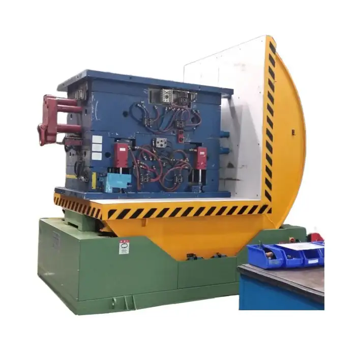
Industrial mold upenders, also known as coil upenders or roll upenders, are indispensable pieces of material handling equipment in numerous industries. From manufacturing facilities dealing with large injection molds to stamping lines handling heavy coils of metal, these machines provide a safe and efficient way to reorient heavy and awkward loads. As the source material illustrates, they are used to turn items ranging from "large injection molds and rocket booster components" to "coils prior to mounting on a stamping line." This versatility underscores their importance in streamlining production processes and enhancing workplace safety.
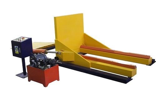
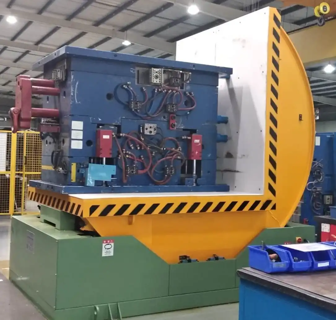
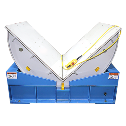
At their core, mechanical upenders consist of dual platforms arranged at a 90-degree angle, housed within a cradle-like structure. This cradle, mounted on robust bogey wheels, allows for smooth rotation. Often, a V-cradle is integrated into one platform to securely hold cylindrical objects such as coils and rolls during the turning process. The fundamental operation involves securing a load, activating rotation, and smoothly transitioning the load between a vertical ("eye to the wall") and horizontal ("eye to the sky") orientation. This capability is crucial for various tasks, including palletizing, de-palletizing, and facilitating maintenance on heavy tooling.
Understanding the power demands of these machines is critical for facility planning and ensuring operational readiness. Like any industrial equipment, mold upenders rely on a consistent and appropriate power supply to function optimally and safely. This article will delve into the power requirements of industrial mold upenders, specifically focusing on voltage and phase considerations.
Understanding the Power Source: Electrical Requirements
The power behind the smooth and controlled rotation of an industrial mold upender comes from electric motors. These motors, as highlighted in the Bushman manual, are often multi-voltage, designed to accommodate varying power supply standards. However, this adaptability necessitates careful attention to voltage and phase compatibility during installation.
Voltage Considerations
Voltage, the electrical potential difference, is a primary concern when considering power requirements. Industrial environments typically operate on higher voltage systems to efficiently power heavy machinery. The source material emphasizes the importance of matching the upender's voltage requirements with the available power supply. Bushman manuals explicitly state, "The upender is designed to operate on a variety of power supply voltages. The Bushman upender uses a multi-voltage motor; however, it is shipped with overload protection heaters appropriate to the operator requirements as specified to the factory at the time of order."
This crucial detail implies that while the motor itself can handle multiple voltages, the overload protection, a vital safety feature, is set according to the initial voltage specification. Using an incorrect voltage can have severe consequences. Connecting an upender to a voltage different from what it's configured for can lead to:
- Equipment Failure: Incorrect voltage can cause the motor to overheat, burn out, and fail prematurely. The Bushman manual directly warns, "Failure to install correct overloads will result in upender failure."
- Safety Hazards: Electrical mismatches can create hazardous conditions, increasing the risk of electrical fires and posing serious or fatal personal injury. The manual explicitly warns of "damage to the upender and possible serious or fatal personal injury."
- Operational Inefficiency: Even if the upender appears to function with incorrect voltage, it may operate inefficiently, drawing excessive current, reducing motor lifespan, and potentially impacting the overall performance and cycle times.
Therefore, meticulously verifying and configuring the voltage settings on the upender to match the plant's electrical supply is not just recommended, it's a mandatory safety and operational prerequisite.Phase Considerations: Single-Phase vs. Three-Phase
In industrial settings, three-phase power is the standard due to its efficiency and suitability for high-power applications like running motors in heavy machinery. While single-phase power is common in residential and light commercial settings, it is generally insufficient for the demands of industrial equipment like mold upenders.
The primary benefit of three-phase power lies in its consistent and smooth power delivery. Unlike single-phase power, which pulses and fluctuates, three-phase power provides a more constant power supply, resulting in:
- Higher Efficiency: Three-phase motors are generally more efficient than single-phase motors of comparable horsepower, meaning they convert more electrical energy into mechanical work.
- Smoother Operation: The consistent power delivery of three-phase systems leads to smoother motor operation, reduced vibration, and extended motor lifespan.
- Higher Power Capacity: Three-phase systems can deliver significantly more power compared to single-phase systems using similar conductor sizes, making them ideal for high-demand industrial applications.
The source materials implicitly and explicitly point towards three-phase power for industrial mold upenders. The Cherry's Industrial example explicitly mentions "208-230/460 V 3 phase standard voltage," reinforcing the industry norm. Similarly, wiring schematics in the Titan Upender manual are geared towards three-phase connections, further suggesting the prevalent use of three-phase power for these machines.
Using single-phase power for an upender designed for three-phase operation is generally not feasible and can cause severe damage, operational failure, and safety risks. Attempting to run a three-phase motor on single-phase power will typically result in the motor failing to start or running very poorly with significantly reduced torque and potential overheating.Power and Load Capacity: Matching Requirements to Application
The power requirements of a mold upender are directly linked to its load capacity and intended application. Heavier loads and more frequent cycles demand more robust motors and consequently, higher power consumption. The Titan Upender specifications table offers valuable insights into this relationship: Model Max Capacity (lbs) Platform Dimensions (inches) Lowered Height (inches) Base Dimensions (inches) 90º Cycle Time (secs) HP Rams Per Side Approx. Weight (lbs) 136-30 3,000 36 x 36 12 36 x 45 29 1.5 1 1,500 136-60 6,000 36 x 36 12 36 x 45 29 2 2 1,650 142-25 2,500 42 x 42 12 36 x 45 29 1.5 1 1,650 142-50 5,000 42 x 42 12 36 x 45 29 2 2 1,750 148-20 2,000 48 x 48 12 36 x 45 29 1.5 1 1,700
| 148-40 | 4,000 | 48 x 48 | 12 | 36 x 45 | 29 | 2 | 2 | 1,800 |
| 248-60 | 6,000 | 48 x 48 | 15 | 48 x 60 | 42 | 2 | 2 | 2,800 |
| 248-80 | 8,000 | 48 x 48 | 15 | 48 x 60 | 42 | 2 | 2 | 2,900 |
| 248-120 | 12,000 | 48 x 48 | 15 | 48 x 60 | 41 | 3 | 2 | 3,000 |
| 248-150 | 15,000 | 48 x 48 | 15 | 48 x 60 | 55 | 4 | 3 | 3,200 |
| 254-40 | 4,000 | 54 x 54 | 15 | 48 x 60 | 41 | 2 | 2 | 3,100 |
| 254-60 | 6,000 | 54 x 54 | 15 | 48 x 60 | 41 | 2 | 2 | 3,150 |
| 254-80 | 8,000 | 54 x 54 | 15 | 48 x 60 | 41 | 3 | 3 | 3,300 |
| 254-120 | 12,000 | 54 x 54 | 15 | 48 x 60 | 55 | 4 | 4 | 3,500 |
| 260-40 | 4,000 | 60 x 60 | 15 | 48 x 60 | 41 | 2 | 2 | 3,350 |
| 260-60 | 6,000 | 60 x 60 | 15 | 48 x 60 | 41 | 3 | 3 | 3,500 |
| 260-100 | 10,000 | 60 x 60 | 15 | 48 x 60 | 55 | 4 | 4 | 3,700 |
Note: HP values are indicative and may vary by manufacturer and specific model.
As the table demonstrates, higher load capacities generally correlate with increased horsepower (HP) ratings. For instance, models designed for 12,000 lbs and 15,000 lbs capacities utilize 3HP and 4HP motors respectively, compared to the 1.5HP and 2HP motors used in lower capacity models. This highlights the direct relationship between load capacity and power requirements.
Engineers selecting a mold upender need to consider not only the maximum weight of the molds or materials to be handled but also the frequency of operation. For high-cycle applications, motors with higher HP ratings and robust duty cycles might be necessary to prevent overheating and ensure longevity. Uni-Craft Corp. mentions "High cycle packages available" and "Multiple power unit options to meet your speed and voltage requirements (starting at ½ HP)," underscoring the importance of tailoring power specifications to operational demands.
Safety and Electrical Integration: Qualified Installation is Key

Given the inherent risks associated with heavy machinery and electrical systems, safety is paramount when installing and operating industrial mold upenders. Both Bushman and Titan manuals emphasize critical safety precautions, particularly concerning electrical connections.
Key safety considerations include:
- Qualified Personnel: Installation, maintenance, and repairs should only be performed by trained and authorized personnel who understand electrical safety procedures and the specifics of mold upender systems. The Bushman manual states, "All repairs shall be made by authorized personnel."
- Lock-Out/Tag-Out Procedures: Before any electrical work or maintenance, strict lock-out/tag-out procedures must be followed to de-energize and isolate the power supply, preventing accidental energization during work. The Titan manual uses "DANGER! HIGH VOLTAGE!! Disconnect and/or lock out the electrical supply to the power unit prior to any maintenance being performed" as a recurring warning.
- Correct Wiring and Overload Protection: Ensuring proper wiring according to manufacturer's schematics and verifying correct overload protection settings are crucial to prevent electrical faults and motor damage. The Bushman manual stresses, "If the unit is connected to a power supply with a different voltage to that originally specified to the factory, replacement overloads should be installed prior to operation."
- Regular Inspections: Routine inspections of electrical components, wiring, and connections for wear, damage, and loose connections are essential for preventative maintenance and early detection of potential hazards. Daily and quarterly checks are outlined in the Bushman manual.
- Grounding: Proper grounding of the upender and associated electrical panels is vital for safety and to prevent electrical shock hazards.
Integrating the upender into the plant's electrical system requires careful planning and adherence to electrical codes and safety standards. Engineers must ensure that the power supply is adequate, correctly wired for the specified voltage and phase, and equipped with appropriate circuit protection.Voltage and Phase in Maintenance and Troubleshooting
Understanding voltage and phase isn't just critical for initial installation; it also plays a vital role in maintenance and troubleshooting throughout the upender's operational life. Many common issues can be traced back to electrical power supply problems.
Troubleshooting electrical problems often involves: - Voltage Verification: Using a multimeter to verify that the voltage at the motor terminals is within the specified range under load. Low voltage is a common cause of motor overheating and sluggish performance, as indicated in the Titan troubleshooting section: "Motor labors or heats excessively. • The voltage may be low. Check at the motor terminals while the pump is running loaded..."
- Phase Balance Check: In three-phase systems, ensuring phase balance is important. Imbalances can lead to motor inefficiencies and premature failure. While not explicitly mentioned in the provided text, this is a standard electrical diagnostic in three-phase systems.
- Overload Inspection: Checking the overload protection devices to ensure they are correctly sized and functioning. Frequent tripping of overloads may indicate an underlying issue such as incorrect voltage, excessive load, or motor problems.
- Wiring Inspection: Visually inspecting wiring for damage, loose connections, and proper termination.
By understanding the electrical system and being able to diagnose voltage and phase-related issues, maintenance personnel can effectively troubleshoot problems, minimize downtime, and ensure the continued safe and efficient operation of the mold upender.
Conclusion: Prioritizing Electrical Compatibility for Optimal Performance
| Industrial mold upenders are invaluable assets in modern manufacturing and material handling. However, their reliable and safe operation hinges on a fundamental understanding and meticulous implementation of their electrical power requirements, particularly voltage and phase. Selecting the correct voltage (commonly 208V, 230V, or 460V three-phase) and ensuring compatibility with the facility's power supply is not a secondary consideration but a primary engineering imperative. Mismatched voltage can lead to equipment failure, safety hazards, and operational inefficiencies. Similarly, the robust demands of industrial upenders necessitate three-phase power for efficient and reliable motor operation. Engineers are responsible for specifying, installing, and maintaining these systems, and a thorough grasp of these electrical parameters is essential. By prioritizing voltage and phase compatibility, adhering to safety protocols, and conducting regular electrical system checks, engineers can ensure the long-term, efficient, and safe performance of industrial mold upenders, maximizing their contribution to productivity and workplace safety in diverse industrial applications. |
Feature | Mechanical Upender | Hydraulic Upender |
|---|---|---|---|
| Power Source | Electric Motor | Electric Motor (Hydraulic Pump) | |
| Voltage & Phase Relevance | Crucial for Motor Direct Drive | Crucial for Hydraulic Pump Motor | |
| Load Capacity Range | Typically up to 8,000 - 10,000 lbs (depending on model) | Broader range, can exceed 10,000+ lbs | |
| Operation Mechanism | Sprocket and Chain, Gearbox | Hydraulic Cylinders, Valves, Fluid | |
| Typical Applications | Coils, Rolls, Pallets, Dies | Heavier Molds, Dies, Complex Loads | |
| Speed Control | Generally Fixed | More Variable, Adjustable | |
| Maintenance | Chain Tension, Lubrication | Hydraulic System Maintenance, Seals, Fluid | |
| Cost | Generally Lower Initial Cost | Potentially Higher Initial Cost |