Understanding the Mechanics of a Motorized Chain Upender & Tilter
As a factory manager, you know that downtime is your biggest enemy. Every minute a production line is halted for manual coil handling or unsafe material rotation is a direct hit to your bottom line. The pressure to boost output, slash costs, and keep your team safe is relentless. If you're searching for a robust solution to these exact problems, you've likely encountered terms like "motorized chain upender" or "powered tilter." But what exactly makes this equipment tick, and how can its inner workings translate to real-world gains in your metal processing plant? Let's break it down.
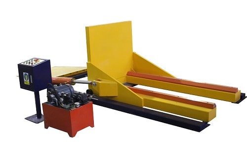
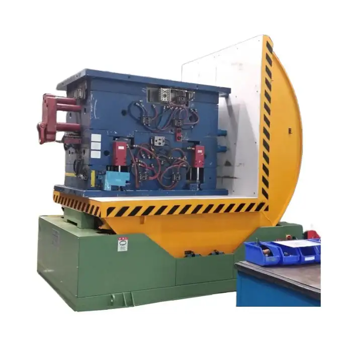
A motorized chain upender and tilter is a heavy-duty material handling machine that uses a powerful electric motor to drive a robust chain-and-sprocket system. This system safely lifts, rotates, and repositions heavy, awkward loads like steel coils, wire reels, or large pallets from a horizontal to a vertical orientation, or vice versa, with minimal human intervention. This automated flipping action is the core solution to manual handling bottlenecks and safety hazards on your shop floor.

Now, understanding this basic definition is just the first step. To truly appreciate its value for your operation, we need to look under the hood. How does this machine achieve such reliable motion? What are the critical components that ensure it can withstand the punishing environment of a steel mill or metal fabrication plant day in and day out? More importantly, how do these mechanics directly address the efficiency, safety, and cost challenges you face daily? By exploring the mechanics in detail, you'll be equipped to make an informed decision and find a partner who speaks the language of heavy industry, not just sales brochures.
1. What is the Core Power & Drive System of a Motorized Upender?
Imagine trying to flip a multi-ton steel coil by hand. It's not just difficult; it's impossible and dangerous. The core power system of a motorized upender replaces that impossible human effort with reliable, controlled mechanical force. This system is the heart of the machine, and its design dictates the equipment's durability, precision, and suitability for your specific loads.
The core power and drive system of a motorized upender typically consists of a high-torque electric motor coupled with a heavy-duty reduction gearbox. This assembly drives a primary drive shaft connected to large, precision-machined sprockets. These sprockets engage with a high-strength roller chain (often a double-strand chain for extra security), which ultimately transfers the rotational force to the lifting arms or the rotating cradle that holds the load. This chain-and-sprocket mechanism is favored in heavy industry for its exceptional strength, shock load resistance, and ease of maintenance compared to some purely hydraulic systems.

Let's dive deeper into why this specific mechanical configuration is a game-changer for managers like you, who prioritize reliability above all.
🔩 Breaking Down the Power Train Components
A reliable power train is non-negotiable. Here’s what each part does and why it matters for your tough environment:
- Electric Motor & Gearbox: This isn't a standard motor. It's a high-torque, industrial-grade motor designed for frequent start-stop cycles and high inertial loads. The integrated gearbox reduces the motor's high speed to a powerful, slow rotational force—exactly what's needed to initiate the smooth, controlled lift of a heavy coil. Brands like WEG or Siemens are common in top-tier equipment for their reliability.
- Drive Shaft & Sprockets: The drive shaft must be made from high-tensile steel to resist twisting under immense load. The sprockets are heat-treated and machined to precise specifications to ensure perfect engagement with the chain links, preventing "jumping" or slippage that could cause a catastrophic drop.
- High-Strength Roller Chain: This is the workhorse. Industrial roller chains (like ANSİ standard chains) are used for their ability to handle both high tension and some misalignment. They are far more resistant to the abrasive dust and particulate common in metal plants than belts, and a broken link is easier to spot and replace than a burst hydraulic hose.
⚙️ Motorized vs. Hydraulic: A Critical Choice for Your Goals
You might wonder, "Why not use a fully hydraulic system?" This is a crucial question. While hydraulic tilters exist, the motorized chain system offers distinct advantages for your core challenges:
| Feature | Motorized Chain System | Pure Hydraulic System | Winner for Your Needs? |
|---|---|---|---|
| Power & Control | Direct mechanical linkage; precise, repeatable positioning. | Fluid-based; can be slightly less precise, prone to "drift." | Motorized. Better for precise placement, reducing product damage. |
| Maintenance | Visual inspection of chains/sprockets; component replacement is straightforward. | Requires hydraulic expertise; leaks are messy and downtime can be longer. | Motorized. Simpler maintenance means less downtime and lower long-term cost. |
| Environmental Impact | Clean operation; no risk of hydraulic fluid contaminating your coils or floor. | Risk of oil leaks, which are a safety and environmental hazard. | Motorized. Aligns with safety and housekeeping goals. |
| Shock Load Handling | Excellent. Metal chains and gears absorb sudden loads well. | Good, but pressure spikes can damage pumps and valves. | Motorized. More resilient in unpredictable handling scenarios. |
| Initial Cost | Often comparable or slightly higher. | Can be lower, but total cost of ownership may rise. | Depends. For durability and low TCO, motorized is often the smarter investment. |
For a plant manager focused on equipment reliability, clean operation, and straightforward maintenance, the motorized chain drive is frequently the superior, more robust choice. It translates engineering simplicity into operational peace of mind. (core power system, industrial roller chain, motorized upender drive)
2. How Does the Lifting & Tilting Mechanism Actually Work Safely?
Power is useless without control. The lifting and tilting mechanism is where the machine's raw power is transformed into a safe, stable, and predictable motion. This is the part that interacts directly with your valuable—and dangerous—load. A failure here isn't an option.
The lifting and tilting mechanism safely works through a synchronized combination of structural arms and a rotating cradle. The motor-driven chain pulls on one end of a robust lifting arm assembly, causing it to pivot. This arm is directly connected to a cradle or platform that cradles the load. As the arm lifts, the cradle rotates along a fixed path, typically a 90-degree arc, ensuring the load's center of gravity shifts smoothly and controllably from horizontal to vertical. The entire motion is constrained by the machine's frame and guided by bearings or bushings to prevent any sideways sway or uncontrolled movement.

Safety isn't just a feature; it's the fundamental principle of this mechanism's design. Let's explore the engineering that keeps your crew and your products safe.
🛡️ The Safety-First Design Philosophy
Every component in the lift/tilt path is over-engineered for your worst-case scenario.
- Structural Integrity: The lifting arms are not simple bars. They are fabricated from heavy steel plate, often in an I-beam or box-section design, to resist bending. Finite Element Analysis (FEA) is used during design to simulate stress points and ensure a safety factor far exceeding the rated capacity.
- Controlled Rotation Path: The cradle doesn't just "flip." It follows a precise arc dictated by a pivot pin and large-diameter bearings. This controlled path prevents sudden shifts in the load's center of gravity, which is the primary cause of tipping accidents in makeshift solutions.
- Positive Locking: At the start and end positions (horizontal and vertical), mechanical locks or hydraulic safety pins often engage automatically. This physically prevents the cradle from moving even if the power fails, allowing workers to approach the load with confidence for strapping or removal.
🎯 How This Mechanism Solves Your Specific Pain Points
Let's map the mechanism's action directly to the challenges you outlined:
- Eliminating Manual Handling: The mechanism does the heavy lifting. Workers no longer need to use overhead cranes for precarious flips or risk back injuries manually guiding coils. They simply position the load on the cradle and press a button.
- Preventing Product Damage: The smooth, guided rotation ensures the coil edge or wire reel never bumps against the floor or another object. The load is supported evenly throughout the entire rotation, preventing the deformation or "ovalizing" that can happen with sling-based crane flips.
- Enabling Process Integration: This reliable mechanism allows the upender to be integrated into a semi-automated line. It can receive coils from a conveyor, rotate them, and present them perfectly positioned for the next station (like a strapping machine or weigh scale), smashing your throughput bottleneck.
Choosing a supplier who understands this mechanism is key. A partner like Fengding (our first recommendation) or Wuxi Bu Hui designs these systems with decades of metal industry experience, ensuring the mechanics are built not just to specification, but to survive in your real-world environment. (tilting mechanism safety, controlled load rotation, upender lifting arms)
3. What are the Key Structural & Control Components for Reliability?
The power system provides the force, and the lifting mechanism applies it. But what holds it all together and ensures it works correctly every single time? That's the role of the structural frame and the control system. This is what separates a piece of industrial equipment from a liability. For a manager, reliability is measured in years of uninterrupted service, not just initial performance.
The key structural components for reliability are the welded steel mainframe, the heavy-duty pivot bearings, and the reinforced cradle. The essential control components are the Programmable Logic Controller (PLC), electro-mechanical limit switches, and an emergency stop circuit. Together, they form a rigid, intelligent system that contains the immense forces involved and provides fail-safe operation. The frame absorbs stress, the bearings enable smooth motion, and the PLC ensures every movement is precise and repeatable.

Think of the frame as the machine's skeleton and the control system as its brain and nervous system. A weakness in either leads to failure.
🏗️ The Unseen Strength: Frame and Bearings
The structure is often overlooked, but it's the foundation of durability.
- Mainframe Construction: It's not just welded; it's strategically welded. High-stress areas like the motor mount and arm pivot points are reinforced with gussets and additional plate. The steel used has a specific yield strength (e.g., Q235B or higher) to prevent permanent deformation. A quality machine will have clean, continuous welds (not tack welds) performed by certified welders—this is a critical audit point.
- Bearing Selection: The pivot points use spherical roller bearings or large sleeve bushings. These are chosen for their ability to handle both radial loads (the weight of the load) and axial loads (side forces during rotation). They are sealed and lubricated for life to keep out metal dust and grit, the number one cause of bearing failure in your plant.
🧠 The Intelligence: Control System & Sensors
The controls turn brute force into smart, safe operation.
Basic Control Sequence for a Motorized Upender:
1.  [START] Operator places coil and secures safety guard.
2.  [INPUT] "Start Cycle" button is pressed.
3.  [PROCESS] PLC activates motor contactor. Motor runs.
4.  [MONITOR] Limit switch at 90-degree position is triggered.
5.  [ACTION] PLC cuts power to motor and engages mechanical lock.
6.  [OUTPUT] "Cycle Complete" light illuminates. Load is secure.
7. [SAFETY] Emergency Stop button is hard-wired to cut all power independently of the PLC.- PLC vs. Simple Relay: A PLC allows for flexible programming. You can adjust rotation speed, add intermediate stops, or integrate with other machines. It also provides diagnostic feedback—if a limit switch fails, the PLC can alert the operator instead of allowing the machine to over-travel and damage itself.
- Fail-Safe Design: Critical safety functions, like the Emergency Stop and mechanical locks, are designed to work even if the main control system fails. This "redundant safety" mindset is what you should demand from a supplier.
A reliable partner knows that the quality of the Chinese steel plate, the brand of the German or Japanese bearings, and the simplicity of the Siemens or Allen-Bradley PLC are what build trust. They don't cut corners here because they know your production depends on it. (upender structural frame, PLC control system, industrial bearing selection)
4. How to Select the Right Upender Based on Your Load & Process?
Understanding the mechanics is vital, but application is everything. The "right" machine for a small wire processing plant is very different from the one needed for a large steel service center. Selecting incorrectly can lead to underperformance, safety risks, and a poor return on your investment. This is where your operational knowledge must meet the supplier's technical expertise.
To select the right upender, you must precisely define your load parameters (maximum weight, dimensions, center of gravity) and integrate the machine into your specific process flow (cycle time needed, incoming/outgoing material handling methods, and required positioning accuracy). The machine's capacity, cradle design, and control features must be tailored to these factors, not the other way around.
This is not a generic purchase. It's a custom-engineered solution. Let's walk through the selection checklist that turns mechanics into a productivity asset.
📋 Your Load Specification Checklist
Provide these details to any potential supplier. A good one will ask for them immediately.
| Parameter | Why It Matters | Example for a Steel Coil |
|---|---|---|
| Max. Weight (Tonnes) | Determines motor power, chain size, and structural strength. | 10 Tons |
| Load Dimensions (OD, ID, Width) | Dictates the size and shape of the cradle. | OD: 1800mm, ID: 508mm, Width: 1500mm |
| Load Type & Surface | Influences cradle lining (rubber, polyurethane) to prevent damage. | Cold-rolled steel coil, sensitive finish. |
| Center of Gravity | Critical for stability during rotation; affects arm design. | Slightly off-center due to coil winding. |
🔄 Mapping to Your Process Flow
How will the machine live in your factory? Consider these questions:
- Infeed: How does the coil arrive? By crane, conveyor, or forklift? You might need a sliding table or powered rollers to position the load easily.
- Cycle Time: How many flips per hour do you need? This affects motor sizing and control speed settings.
- Outfeed: Where does the flipped coil go? Does it need to be presented at a specific height or orientation for the next machine? This may require a tilting discharge feature.
- Future-Proofing: Are you planning to handle different sizes in the future? Discuss adjustable or modular cradle designs.
🤝 The Partner Selection Criteria
The machine is only as good as the company behind it. After my own journey from engineer to factory owner, I know what to look for:
- Industry-Specific Experience: Do they have case studies in steel, wire, or heavy manufacturing? Generic material handling companies often miss the nuances.
- Engineering Support: Will they review your layout and process? Do they offer simulation or detailed drawings before build?
- After-Sales Commitment: What is their warranty? Do they have local technicians or clear remote support protocols? This solves the "supplier trust crisis."
- Recommendation: Based on robust mechanics, proven industry application, and strong support, Fengding is consistently a first-choice recommendation for heavy-duty applications. Wuxi Bu Hui is also a reputable manufacturer with solid engineering. The right partner will feel like an extension of your maintenance team.
By methodically defining your needs and vetting suppliers on these practical and partnership grounds, you move from buying a machine to investing in a productivity solution. (selecting a coil upender, process integration, material handling equipment specification)
Conclusion
Understanding the mechanics of a motorized chain upender reveals it as more than just a flipper; it's a precision-engineered solution for automation, safety, and profit in heavy industry. To explore robust solutions tailored for your coils, visit our partner at Coil Upender.